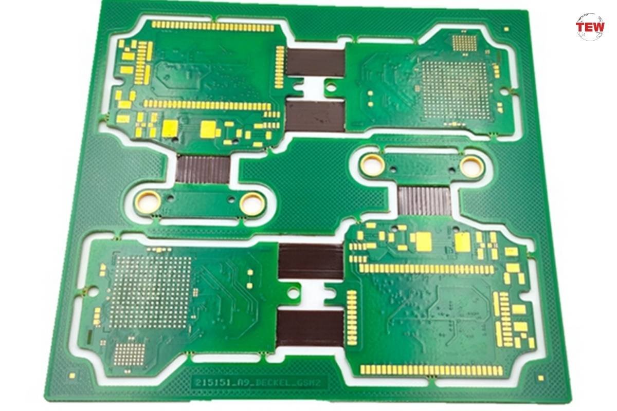
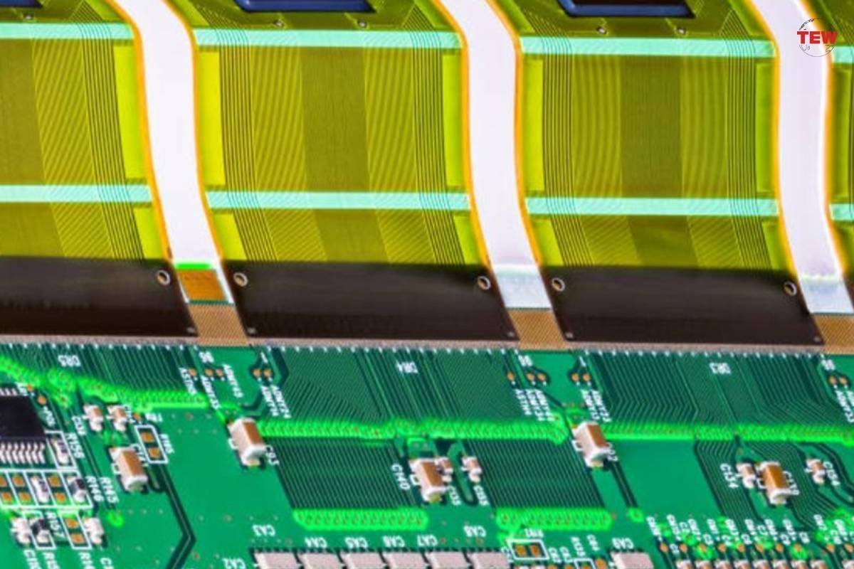
The origination of the rigid flex PCB represents how far has modern electronics manufacturing evolved. This PCB combines the integrity of rigid circuit boards while at the same time, the flexibility of flex circuits. However, creating this remarkable component in modern electronics is no easy feat as it involves a very intricate process that combines the traits of rigid and flexible PCBs into one unit whose components work in harmony.
In this article, we’ll be exploring the step-by-step assembly process for rigid-flex PCBs to understand the complexities of this circuit board and appreciate this technological marvel.
Why use a Rigid-Flex PCB?
Before we explore the steps in assembling a rigid-flex PCB, let’s understand why companies and organizations enjoy harnessing the potential of this type of circuit board. The reasons can range from the following listed below which are:
- Space-saving: In comparison to conventional PCBs, rigid-flex boards occupy less space and eliminate the need for wires and connectors that may tangle inside the electrical configuration.
- High signal integrity: This type of printed circuit isn’t prone to issues such as signal degradation or interferences making it capable of maintaining processes that were inputted on the device it is integrated to.
- Durable and made to last: Compared to conventional circuit boards, rigid-flex PCBs are more resilient against mechanical stress which makes them suitable for mechanical applications where lasting longer is crucial. For example, inside factories where the assembly lines could strain standard PCBs in the long run.
- Cost-effective in the long run: The base cost of purchasing these boards from a rigid flex PCB manufacturer may seem higher than standard PCBs, but these expenses can be lowered as rigid-flex boards require fewer components to properly function and have a shorter assembly time on average.
- Design flexibility: One of the main appeals of using rigid-flex circuit boards is their flexibility in design. The combination of rigid and flexible sections enables electronic brands to come up with creative product designs that are compatible with these PCBs.

The steps in assembling a Rigid-Flex PCB:
Be aware that the process of assembling a rigid flex PCB can be meticulous and very technical. In this section, we’ll cover the procedures for properly assembling that type of printed circuit board, but we’ll explain them in a more digestible form so you can quickly understand them.
1. Addition of adhesive coating and copper foil
The first step in assembling a rigid-flex PCB is the application of an epoxy or adhesive coat to the laminate material. This is followed up by the addition of the copper foil onto the laminate which will stick due to the previously added adhesive. However, there’s an alternative in which you can use rolled annealed copper instead if you aren’t a fan of adding adhesives to a blank PCB laminate.
2. Drilling in the holes on the board
The next step in assembling a rigid flex PCB is to drill holes in the laminate surface which leads to the vias and pads linked to the board. However, drilling this type of PCB can go in multiple ways – for instance, you can use combined flex panels that were cut in advance wherein they are drilled in between two rigid blanks.
In a similar vein, multi-plated flex substrates for this type of PCB are drilled at the same time when they are fused from more than one reel on the drums where drilling takes place between the work plates before it is rolled out to different reels which are on opposing sides of the drilling machine.
3. Inclusion of copper plating
Once the drilled holes are in place, the next step in assembling a rigid flex PCB is to add the copper plating which is done by chemical means and in the same fashion as the cores found on rigid printed circuit boards. The plating must be 1 millimetre thick at a minimum so that it can offer support on the vias or pads present on the PCB.
Alternatively, if it is a budget rigid-flex circuit board, the plating thickness can be only up to half a millimetre thick.

4. Etching in the traces
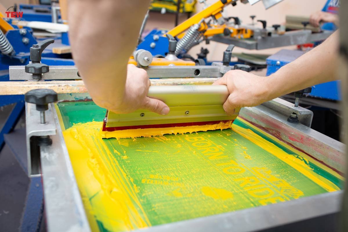
Once the copper plating is added to the rigid flex PCB, the next step is to set up the copper traces that will become the circuit board’s patterns. This is done through the addition of a light-sensitive etch resist on the film surfaces of the circuit board. Once it is added, a stencil pattern is used to expose the etch resist to light to the specific parts of the board.
After exposing those parts, the PCB is developed which means the resist surface is removed. The last phase of this step is to etch away the excess copper through chemical means in which the remaining copper traces will become the patterns present on the PCB’s surface.
5. Covercoating the PCB
Once the copper traces are given a finish, the penultimate phase involves cover coating the printed circuit board. This is kickstarted by protecting the flex circuit by having it covered on the top and bottom layers with thin protective sheets called the coverlay. Then, the coverlay is cut to fit the shape of the flexible circuit – think of it as trimming a piece of paper to match a drawing’s outline.
To finalize this step, the covercoat is exposed to ultraviolet light which will harden it and make it more capable of protecting the components sandwiched between them.
6. Separate the flex printed circuit board
The next step in making a rigid flex PCB is cutting it to its right shape which is called “outline cutting”. This step can go in two ways depending if you’re manufacturing in bulk or low volumes. For bulk production, a hydraulic punch and die set are utilized – think of them as hole punchers that can cut out many PCBs at the same time making it efficient but expensive because the tools can be a hefty investment.
Now if you’re working with a small quantity of rigid flex circuit boards, you can use a specialized blade called a blanking knife. You will mount the blade on a board and you will press the flex circuits onto it so it can be cut to its desired form. Also, flex PCB can be cut by laser, but it is more expensive.
7. Assembly components on the rigid flex PCB
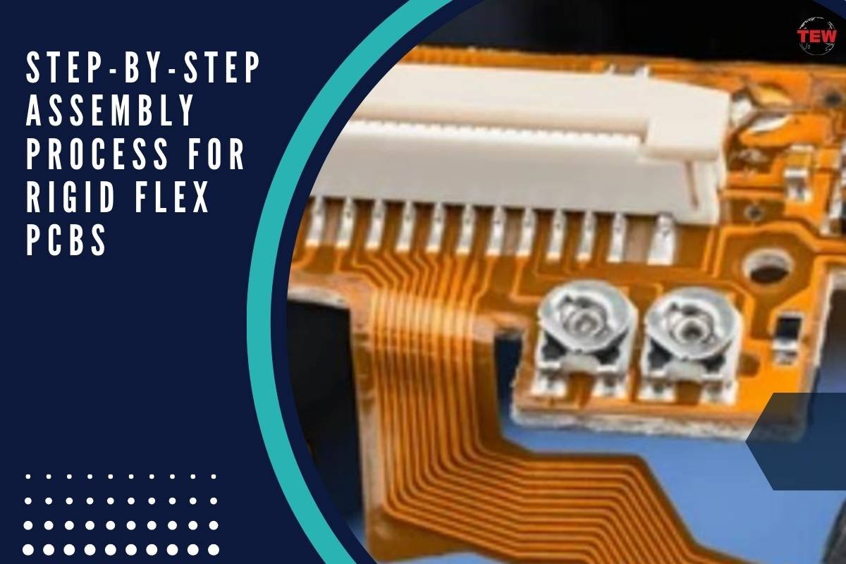
When the bare flex PCB is finished, we can assemble the electronic components on the flexible PCBs, both PTH assembly and SMT assembly can be used. But we need to know that a lot of tools or supporting plates may be needed since rigid flex PCB is not flat.
8. Quality inspections to after rigid flex PCB assembly
After PCB assembly, a full rigid flex PCB is finished. But we need to do a lot of testing and inspections to ensure good quality, such as E-testing, AOI inspection, X-ray inspection, ICT testing, functional testing and also visual inspections.
An intricate but worthwhile addition to any device
To summarize what we’ve covered, a rigid-flex PCB combines the best traits of a rigid PCB and a flexible circuit board into one powerhouse of a unit. However, creating this circuit board requires it to undergo complex processes. The assembly process is kickstarted by the addition of coating on a blank laminate board and ends with blanking the PCB to a form that will fit in with the electronic configuration of a device.
Once finished, this new flex rigid PCB can be introduced to the device that it is intended for and will ensure its proper functioning for a long time.


